Help File Topic Links
Zeroing the FP1 The FP1 needs to be zeroed often, this shows you how
Sleep, waking the FP1 The sleep feature will save your battery if you forget to turn off your FP1
PS3 pressure sensor 3 Optional pressure sensor 3 (PS3) information
Velocity Probe A velocity probe can be used on the standard FP1, or with optional PS3
FP1 to PC Connection Connecting the FP1 to your PC
FPcom Software FPcom is the Windows PC software that operates your FP1
Status Bar The FPcom status bar shows you important FP1 settings.
Data Capture There are several ways to capture data
FPconfig file Reassign the cells that data will be sent to with a config file
FP1 general information The FP1 is the electronic box that measures the flow rates in your flow bench
FP1 data entry How to enter and change FP1 settings and operating parameters
FP1 to Bench connections Information on connecting FP1 to flow bench
Flow Performance system connection
Flow Bench Operation Flow bench operating procedure
Flow Bench Calibration Information on calibrating your flow bench
PWM Port, Aux3 The PWM port (Aux3) controls a PWM motor for automatic test pressure
FP1 Command Summary A brief listing of commands and their functions for quick reference
FP1 command list Listing of all FP1 data and parameter commands
____________________________________________________
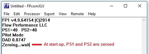
Zeroing the FP1
The pressure sensors of
the FP1 will drift with time and temperature. They need to be re-zeroed from
time
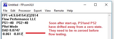
to time, and especially soon after start-up or before
doing any calibration or flow testing. The FP1 provides the user
the ability to view the zero state of the sensors,
and to easily re-zero the sensors with the touch of a button.
The sensors must be zeroed only when absolutely no pressure is being applied
to
them. Do not move the
pressure tubing or velocity probe or FP1 while zeroing.
Make sure your flow
bench is completely powered down, and that the hoses connecting your bench
to the FP1 or to a velocity probe are not moved
during the zeroing process.
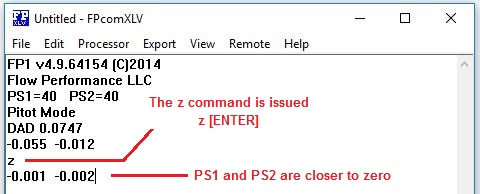
Press the z (lower
case) key, then RETURN or ENTER.
The FP1 should report
“Zeroing…wait” for about 2-5 seconds.
The FP1 should then
continue reporting pressure sensor readings that should be closer to .000
In all modes of
operation, PS1 and PS2 assume a .001 resolution manometer mode when no pressure
is
Applied (high pressure
sensors may display a .01” resolution). PS1 is represented in column one of the
readout,
and PS2 in column two. This provides the user a view
of the zero state of the sensors when there is no pressure applied.
Before
doing any flow testing, it is a
good practice to run your pressure up to the intended test pressure for a
moment,
then to release the pressure to zero pressure, and
then zero the processor.
Bounce: The
sensor readings will tend to “bounce” and a steady zero state of .000 should
not be expected.
The amount of bounce
depends greatly on the sample duration setting (s, or S) and the
range of the sensor
installed into your FP1. Typically, for a sample duration
of 50 (maximum, 20 in earlier model FP1s), the bounce
is about .003”wc for 40”wc sensors and .01”wc for
higher pressure sensors.
Hard
Zero (Z) If the pressure on PS1 has drifted higher than
.1”wc (or greater than the value of p on later
versions), the FP1 will go into System-On Calibration if
you try to zero the FP1. For this reason, Hard
Zeroing will cause the
FP1 to zero the sensors no matter what the pressure on PS1.
To cause a Hard Zero,
press the Z (UC) key, then ENTER or RETURN.
Sensor
drift
The sensors will drift
dramatically at start-up for about 30 seconds, then
continue to slowly drift for several
minutes. This is normal, as the sensors are adjusting to
the heat created within the electronic circuits of the
FP1.
Temperature change is the
main reason for sensor drift. If the ambient temperature is changing, the
sensors
will tend to drift at a higher rate. To minimize
drift, place the FP1 in a location that will not be subject to
rapid changes in temperature. Do not place near
exterior walls, AC or heating ducts, large appliances or
machinery.
Troubleshooting
Excessive Bounce and Drift in zero state (no pressure applied)
The FP1 sensors may act
erratically for several hours after being moved or repositioned. Allow time
for the sensors to settle.
Check pressure tubing
for moisture, condensation or water in the lines. Try replacing them.
Keep away from exterior
walls, heating and cooling ducts, large machines and appliances.
Do not place FP1 on a
surface that moves or vibrates.
Try relocating the FP1.
Wiring inside a wall or a large appliance or machine nearby may be creating
interference.
___________________________________________________________________________________
Sleep, waking up the FP1
It is important to use the sleep feature to prevent your battery from running down if you forget to turn off your FP1.
When the FP1 has not
received any input from the user or detected any pressure greater than .1”wc on PS1
(or
pressure greater than the value of p on later versions) for a duration
determined by the FP1 sleep timer
value (o), the FP1 will enter a sleep mode to
conserve battery life. The FP1 will report “Sleeping” when it
has entered sleep mode.
To
awaken FP1 form sleep mode, press any key on your keyboard
When the FP1 resumes
operation, it will zero the sensors and continue operation.
When the FP1 enters
sleep mode, FPcom will start a 5 minute timer. If the
FP1 is not awakened within 5
minutes, FPcom will turn off
the processor and display a message “Sleep Timer Expired”.
To
restart an expired sleep timer,
from the Fpcom menu select Processor | Proc On.
You can disable the
sleep feature on later model FP1’s by setting sleep timer (o) to zero. But if
you forget to turn off your FP1,
it will remain on
until your battery is dead.
___________________________________________________________________________________
FP1 to PC Connection
The FP1 connects to a
Windows 95 and later PC serial port. Serial ports are the D shaped plugs with 9
pins.
If you do not have a serial port, you should have a USB port. You can buy a USB to serial converter to run your FP1 from a USB port.
If using a USB serial adapter, make sure the adapter uses
the FTDI chip set. Read the instructions
that come with your adapter for installation.
Connect your FP1 Serial
I/O port to your computer serial port. Use the serial cable supplied with your
FP1.
If you do not have this
cable, you will need a F/F Null Modem 6’ cable.
You may use an extension
cable on your serial cable, but try not to exceed 10’.
If you have any trouble
with your FP1, try removing the extension cable.
When you start Fpcom, the FP1 should start sending text to the Fpcom document screen.
In the lower left hand
corner of your Fpcom screen, there is a small box
that reports your serial port connection with the FP1.
These are the messages
that will appear in this box, where # is the port number:
OFF The serial port is closed and the FP1
is off
ON# Fpcom was
able to open the # serial port
CK# Fpcom is
looking at the # serial port for the FP1 (FPcomXLV
only)
RC# Fpcom has
received data on the # serial port from the FP1
If FpcomXLV
is not able to find the FP1 on any serial ports, a message box will appear
showing you a report of the serial port search for the FP1.
You can also access this
report from the Processor | Serial Report menu item.
“Cannot
turn off your PC, disconnect your FP1 from the PC,
turn on your PC, when your PC finishes booting-up, reconnect the FP1 to the PC
serial port and try again.
If this solves the problem,
your PC is detecting the FP1 as a serial device, probably a serial mouse. If
you are good with computers,
you can go into Device Manager and find what it is
that your computer thinks the FP1 is (usually a serial mouse), and disable that
device.
ActiveSync, a program form Microsoft to communicate with
portable computers, can make connecting to the FP1 very difficult.
If you have ActiveSync on your computer, try disabling the serial
communications and reboot your computer.
___________________________________________________________________________________
FPcom Software
FPcom software operates your FP1 flow rate processor
from a PC. FPcom runs on Windows 95 and later powered
PC’s.
It is a text based
program that is very similar to a simple word processor like Note Pad.
There are several
versions of FPcom… FPcomXLS,
FPcomXLT and the latest version is FPcomXLV. All these versions can send
your FP1 data directly into an Excel spreadsheet in
real time as you flow test. FPcomXLV has enhanced
features for using a
velocity probe and Excel. See the section Excel for more information on using
Excel with FPcom.
FPcom makes it possible to do just about everything
using just a keyboard. This is because using a mouse in a shop
environment or on a flow bench is not always possible or
practical.
When you start FPcom, the program will try to find the FP1 on the
available serial ports of your computer.
When it has found the
FP1, the FP1 will start sending text data to the FPcom
document screen:
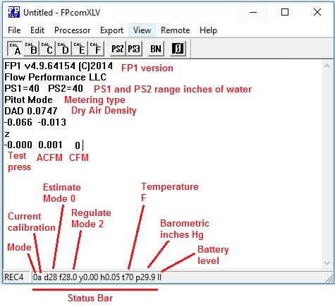
The status
bar is located at the bottom of the FPcom
document screen. It shows you important FP1 settings that will affect your flow
rate readings…
1A d28 f10 h.05 t70 b29.9
y0.0 III
1A < The number (1) is the current mode of operation. The
letter (A) is the currently selected calibration.
Upper case letter denote
Orifice bench is selected, lower case letter denote Pitot
bench selected.
d28 <
This shows the test pressure that the FP1 will estimate flow rates to
when in mode 0
f28 <
A center value for establishing a test pressure window for regulating
pressure Mode 2
h.05 <
This is used along with f to establish a test pressure window
t 70 <
This is the temperature entered by the user or by a temp sensor. Used to
calculate air density and
ACFM
p29.9 <
This is the barometric pressure entered by the user. Used to calculate
air density and ACFM
Note, p is used in the status bar, but
Barometric is accessed with the b command
Y0.0 <
this is a data reading damping value
III <
This is the battery level. III = good battery, I = weak battery, BAT
battery almost dead.
See the section FP1 Command List
for more details on the status bar values.
When you enter commands
to the FP1, they will be saved in the FP1, and will remain there even after you
turn off the FP1.
FPcomXLT and FPcomXLV features
a Big Numbers feature. Select menu item View | Big Numbers to enable this
feature.
You can drag the Big
Numbers window to any place on your screen with your mouse.
Data Capture There are several ways to capture
data.
Space bar data
capture will mark the current
line of data on the FPcom document screen with a
numerical value that is entered into Q,
then a new line of data is started and the value of Q
is incremented. If Q is set to 0.1, then the data on the FPcom
document will be
marked with each press of the space bar as shown below:
28.0
234.5 236.7 <Mark 0.1
28.0
234.8 237.0 <Mark 0.2
28.0
234.4 237.3 <Mark 0.3
The Mark value is reset
to Q each time the FP1 is zeroed.
If Excel is enabled, the
data is also sent to Excel with each press of the space bar and the row is
incremented with each capture.
Remote Mouse is featured on FPcomXLT
and FPcomXLV. Remote Mouse makes your mouse into a
remote data capture button.
A wireless mouse gives
you more freedom and perhaps range. It works just like the space bar except you
press the mouse left button to capture data.
Enable Remote Mouse by
selecting menu item Remote | Mouse. When Remote Mouse is enabled, a red box
will appear that will contain your mouse pointer.
Press the keyboard Esc
button to turn off Remote Mouse.
You turn off FPcom by clicking on the (X) icon in the upper right hand corner of the FPcom screen, or by selecting menu item File | Close.
When you quit FPcom, you will be asked “Save Changes to Document”.
This is asking you if you want to save the data that is on the screen as a text
file,
it has nothing to do with any changes you may have
made to your FP1 settings. If you do save your FPcom
document, add .txt to your file name
so that you can open your documents in other
applications like word processors or an Excel spreadsheet. Example: MyFlowTest.txt
If you do not want to
save your data on the FPcom document as a text file,
select NO.
See the section FP1 to
PC Connection for more information on connecting your FP1 to your PC and
information on serial ports.
See the section FP1 Commands and Data
Entry for information on controlling your FP1 through FPcom.
Note: if your FPcom software appears to freeze-up or become
non-responsive while entering commands,
see
your FPcom Help menu item “USB Connection”.
___________________________________________________________________________________
PS3 pressure sensor 3 (Optional)
FP1 version 3.17.32 and higher, supports a third pressure sensor in the FP1, pressure sensor 3, or PS3. PS3
can be used to measure flow velocities while flow volume rates are being measured on PS2.
PS3 is enabled by setting (a) to 1 (one).
PS3 is disabled by setting (a) to 0 (zero).
When PS3 is enabled, the data reading rate from the FP1 is slowed. This is because of the time required to
sample and process PS3.
If PS3 is disabled, make sure there is no pressure applied to all pressure sensors when enabling PS3. The
FP1 will enter the zeroing function when PS3 is enabled.
(v) is a trim multiple of the velocity reading. Be sure v is set to 1.0 if no adjustment is desired.
(V) determines velocity reading format. V = 1 feet per second. V = 0 feet per minute. Velocity readings in
feet per second are appended with an s (Example: 240s).
Mode 0 will estimate the velocity to the test pressure
entered into d.
Back
______________________________________________________________________________________
Velocity Probe
Click here to see velocity probe connection information.
A velocity probe can be
connected to the FP1 PS2 sensor. An optional pressure sensor
, PS3, can be installed into the FP1 for connection of a velocity probe.
While PS2 only gives you
the ability to read cfm from your flow bench or
velocity from your velocity probe, PS3 allows you to read cfm
from your
bench and velocity from your probe at the same time.
Velocity probe
correction can be entered in v
(lower case). Your velocity readings will be multiplied by the value of v. If
no correction is required,
or not known, set v to 1.0.
Feet/Second or
Feet/Minute is selected with V
(upper case). V = 0 (feet/minute). V = 1 (feet/sec). Velocity readings in
Feet/Sec will be appended with an s.
Mode 0 will estimate the velocity to the test pressure
entered into d.
Mode 1,2 and 4 will display the velocity relative to the actual
test pressure.
PS2
Connect impact port of probe to PS2+, and static port of probe to PS2-.
(If you get a test pressure reading and velocity reads zero when probe is inserted into an air stream, the probe is probably connected wrong).
Select calibration P. A fourth column of data should now appear on the FPcom document, velocity.
PS3
Make sure Calibration P, CAL P, is NOT selected.
Connect impact port of probe to P3+, and static port of probe to PS3-.
(If you get a test pressure reading and velocity reads zero when probe is inserted into an air stream, the probe is probably connected wrong).
Enable PS3 by setting a (lower case) to 1. Enabling PS3 will cause a forth column of data to appear on the FPcom document, which is velocity.
Enabling PS3 will slow down the FP1, so disable PS3 if not needed.
Not getting velocity
readings try reversing the
connection of the probe to the FP1.
If using PS2, make sure
calibration P is selected and a is set to 0 (zero).
If using PS3 make sure calibration
P is not selected, and that PS3 is enabled (a = 1).
_____________________________________________________________________________________
Excel
FPcom will
allow you to transfer the data from the FP1 flow processor directly into an
Excel (r) spreadsheet in real time as you flow test.
The
spreadsheet can be used to display the data, or to further process the data.
Make sure you are familiar with
your flow bench operation and using FPcom software
before attempting to use Excel.
Trying to use Excel when not
familiar with your flow bench and software can be a confusing and frustrating
experience.
The
spreadsheet that will receive data from Fpcom must be
named FPexcel.xls, and it must be located in the same location (drive, folder)
as FPcom.
You start
your Excel spreadsheet by selecting [Export | Excel] from the menu.
When you use a capture method
(Remote Mouse or keyboard space bar) the
data from FPcom will be sent to the top row of your
spreadsheet, starting at cell A1.
From the top row of the Excel sheet,
the data can be copied to other cells and further processed, in real time, as
the data is received by programming the Excel cells.
Error message: If you get error messages when Fpcom tries to launch your spreadsheet, from the Excel
program, open and then save your spreadsheet to
the folder
that FPcom is located. This will insure Excel knows where your spreadsheet is located.
Error message: If you
get a warning from Excel about macros within your spread sheet, you can set the
security settings for your
Excel program to a lower setting,
(only if you think your Excel sheet is safe).
You can
enable the arrow keys on your keyboard for velocity mapping (FPcomXLV)
by selecting menu item Export | VPExcel.
The default
starting cell for arrow key velocity mapping is A35.
Excel power users
Always
reserve the entire row 1 for receiving data from Fpcom. The amount of data sent to row 1
may increase in future releases of FPcom software.
Data will currently
go into your spreadsheet cells in this order by default:
A1 test pressure
B1 acfm
C1 cfm
D1 velocity
E1 mode
F1 calibration
C12 captured data start cell (z) Row will increment with each capture
I12 Captured data start cell (Z) Row will increment
with each capture
A35 Velocity mapping start cell. Row or
You can
reassign the cells that data will be sent to by creating a text file named FPconfig.txt (use Note
Pad) and locating it in the same folder as FPcom.
Include text in your FPconfig.txt file to indicate where
data should be placed. Below is a sample of the default settings:
R01C01
R01C02
R01C03
R01C04
R01C05
R01C06
R12C03
R12C09
R35C01
In the above sample, the first entry, R01C01 assigns the test pressure data to row 1 col. 1 (A1) and the last entry assigns velocity mapping start cell to A35.
If you do
not want a particular data item to be sent, use 00 for a row or column number,
that data item will not be received by your spreadsheet.
You can
check the assignments of your FPconfig.txt file by selecting the FPcom menu item [EXPORT | EXCEL CONFIG].
You can
make your spreadsheet launch automatically when FPcomXLV
is started by creating
a text file named excelon.txt (use Note Pad) and locating it in the same folder
as FPcom.
You can make
your spreadsheet appear on top of FPcom when started
by including the text EXCELONTOP in your excelon.txt file. Otherwise FPcom will remain on top of your spreadsheet.
You can
enable the keyboard arrow keys for velocity mapping on your spreadsheet by including the
text VPEXCEL in your excelon.txt file.
_________________________________________________________________________________
FP1 General information
The FP1 is not to be
used for measuring pressures of flammable gasses or gasses containing flammable
particles.
Warning:
The FP1 is not
intended for use in "
tool as well as a
measuring device. Because of this, the FP1 allows the user to configure and
adjust many
settings and parameters
of the FP1. While every attempt is made to check the user settings and
parameters
for valid entries, it is
not possible to anticipate every possible combination for validity of data
input by the
user. The user is
responsible for checking the validity of all data parameters and that the
processor is
functioning properly at
all times.
Flow Rate Detection
The FP1 is designed to
process the differential pressure obtained from pressure differential producing
flow
measuring devices,
specifically, Pitot tube type velocity measuring
devices or a measuring orifice.
PS2 (pressure sensor
2) is used to measure the actual
differential pressure from the differential pressures.
PS1 (pressure sensor
1) is used as a reference
pressure port for measuring test pressures and calculating
standard flow rates. It
is also used as a trigger for some modes of operation. For instance, in modes 0
- 2,
the user can set a
threshold pressure on PS1 to scroll the FP1 readings down the display screen
when that
pressure is met or
exceeded. The FP1 also monitors PS1 for pressures greater than .1”wc to trigger
other
activities, such as
resetting the FP1 processor sleep timer.
Optional PS3
(pressure sensor 3) is for use
as a dedicated velocity probe sensor. You can use a velocity probe on PS2, but
you will not be able to get your
cfm readings
from your flow bench. Using PS3 for a velocity probe allows you to get your
flow bench cfm and your velocity probe readings at
the same time.
Pressure sensors PS1
and PS2, (and optional PS3)
Maximum allowed applied
pressure is 11psi (about 300”wc).
Negative pressures
should not be applied to the positive pressure ports.
Positive pressures
should not be applied to the negative pressure ports.
Pressure readings are
always displayed as a positive value, even when a negative pressure is applied to the negative pressure port.
Modes of Operation
The FP1 has 5 modes of
operation. Modes 0 - 2 are flow rate calculating .
See the section “FP1
Command List” “m” for more information
on mode, or click here for more information on mode.
Power Requirements
The FP1 uses a 9 volt
battery for power. This battery should be an alkaline type for about 25 to 35
hours of
normal use (depending on
installed options and modes of operation). A Ni-Mh
rechargeable battery is recommended for “Power Users”.
The FP1 has a user
programmable sleep mode that will help prolong battery life and prevent the
battery from exhausting if the user forgets to turn off the FP1.
The sleep timer value (o)
has a range between 1 and 255 seconds.
___________________________________________________________________________________
For connection diagrams, see your FPcom Help menu item “Setup Configurations”.
Click here to
see setup configurations
The FP1 PS1 connects to
your receptacle or settling chamber test pressure port.
PS2 connects to your
flow measuring device impact and discharge or static port.
The impact port is the
port that is on the side that air will be entering, or impacting, while the
discharge port is the side of the device that the air will be discharged.
In bi-directional
applications, the impact and discharge ports change with the direction of the
airflow.
Use these conventions
below in determining how to connect your orifice bench to the FP1.
Flow Performance System Connections
(FP2.0BS, FP2.5BS)
Click here for setup information
The FP1 PS1 connects to your bench receptacle, and PS2 connects to your
flow element.
For forward flow (Vacuum
applied to bench) connect the FP1 in the following way:
PS1- to receptacle
PS1 + unconnected (open)
PS2+ to flow element + port
PS2- to flow element – port
For reverse flow (+
pressure applied to bench) connect the FP1 in the following way:
PS1+ to receptacle
PS1 – unconnected (open)
PS2+ to flow element – port
PS2 - to flow element + port
Orifice and other flow element Connections
For forward flow (Vacuum
applied to bench) connect the FP1 in the following way:
PS1- to receptacle or settling chamber
PS1 + unconnected (open)
PS2+ to flow element or orifice impact side
PS2- to flow element or orifice discharge side
*Center blower benches:
PS2 + connects to orifice chamber
PS2 - open
For reverse flow (+
pressure applied to bench) connect the FP1 in the following way:
PS1+ to receptacle or settling chamber
PS1 – unconnected (open)
PS2+ to flow element or orifice discharge side
PS2- to flow element or orifice + impact side
*Center blower benches:
PS2 - connects to measuring orifice chamber
PS2 + open
If you
get a test pressure reading, and your cfm reads zero PS2 is probably connected backwards.
________________________________________________________________________________
Flow Bench Operation
The following is general testing procedures used when testing
internal combustion engine over head valve cylinder heads.
It may include or omit some procedures that may be important
to your specific testing requirements. Your testing specifications may differ.
Preparation
Always wear approved eye protection when
operating your flow bench.
Always keep your
bench area clear of any objects or substances that could fall into the
receptacle.
Never look into the
receptacle while air pressure is being applied.
Disable the air
source before inspecting the inside of the receptacle.
Always check the
receptacle for objects or substances that may have fallen into the receptacle
before applying air
pressure.
Always do your
exhaust port testing first, and quickly, while your air source air is cool.
It is important to check
your equipment before doing any flow testing to ensure everything is working
correctly. The easiest
way to do this is to flow test a calibration orifice for proper flow rates, and
to make
any minor adjustments to
calibration before testing.
The most common reason
for errors in flow testing are caused by air leaks. Since the FE series flow
elements are not capable
of measuring air flow down to zero, no reliable method of leak testing is known
at
this time. It is up to
the operator to ensure that air leaks are not occurring.
When starting the FP1
flow processor, it will take a minute or two for the pressure sensors to settle
down
before they can be zeroed properly. Sometimes they will
loose their zero state after having pressure
applied. For this
reason, it is always a good idea to flow a calibration orifice and re-zero the
FP1 before
doing any flow testing.
Connect the FP1 to
your bench in the proper fashion
(see Flow Bench Connections for more info)
Set your FP1 for the correct
calibration and mode. Flow
Performance systems typically use cal A for forward flow, and cal B for reverse
flow.
If you are not
regulating your test pressure you will probably want mode 0 (zer0), otherwise
mode 1 or 2 should be used.
Check the FPcom status bar to make sure you are in the correct mode
and that all your parameters are appropriate for your flow test.
Zero the FP1 before
doing any testing
Test Piece
Preparation
The most common way of
mounting a test piece to the receptacle is by using C clamps or similar
clamping
devices. Do not over
tighten the clamps. Just snug them down. Over-tightening the clamps may
distort
the surface that the
receptacle is mounted to, causing air leaks or damage.
Make sure your test piece
is mounted with an even clamping force and not cocked or skewed.
Check the receptacle
gasket for bits of debris or for bumps or an uneven surface before mounting the
test
piece.
Make sure the sealing
surfaces are clean and smooth. If you need to use grease on the rubber gasket,
use
only a water based jell.
Oil based grease will destroy the rubber gasket.
On cylinder heads, apply
grease to both valve stems, the valve seat of the valve that will not be flow
tested
and to the threads of
the spark plug or the plug that will seal the spark plug hole. This will help
ensure these
areas will not leak air.
Prepare your test piece
before mounting the head on your bench. Installing your valve depression device
and any clay radiuses
onto your test piece is usually much easier before mounting the piece.
Zero the FP1 before
doing any testing
Always wear eye
protection when operating your flow bench.
Always use vacuum to flow test an item if possible. Use
positive pressure only if using vacuum is not practical.
Positive pressure sources often create rapidly changing
air temperature and initial velocity.
Because most air sources heat the air that they
supply, it is important to follow some
special procedures when testing in the exhaust mode.
It is important to do
your exhaust flow testing
first, and quickly.
By testing your exhaust
port before the intake port, your air source motor will not yet be hot and will
not
heat the air too much.
Don’t let the air source
run while not testing. The longer your air source runs, the hotter the air will
become. Only run the air
source while actually testing, then turn it off if more exhaust testing is
expected.
Mounting the test piece
for exhaust testing most be done very carefully because the air pressure will try
to
push pieces apart, where
vacuum pressure tends to pull them together. Also, as the air heats things,
things
tend to change.
An extension to the
exhaust port will dramatically affect your readings. Any change you make to the
extension, diameter,
length, position, curvature and direction of any curvature will affect your
flow
readings. If using an extension, be sure to document it in detail for others to duplicate your test. Also include flow data not using the extension.
Zero the FP1 before doing
any testing
It is important to do
exhaust port testing first. This is because most air sources heat the air in
exhaust mode
and the exhaust should
be tested before the air source exhaust air becomes too hot.
Make sure you have installed
a radius to the port entrance before mounting your test piece. You can use clay
or plumbers putty to make a radius,
but most children’s clay has a lot of corrosive
properties, do not leave on your test piece.
Plumbers putty is oil
based and should not corrode your test piece if left on.
Adjust your air source
to create a negative air pressure (vacuum).
_____________________________________________________________________________________
Flow Bench Calibration
The FP1 has provisions for 6 calibrations. These calibrations are assigned letters A, B, C, D, E and F.
Flow Performance flow bench systems usually use Cal A for forward flow, and Cal B for reverse flow calibrations.
Calibrations are selected with the M command, and starting with FPcomXLV, by selecting the calibration from the Fpcom tool bar or by using
the Ctrl key and calibration letter.
The selected calibration is displayed as the first set of data on the Fpcom status bar along with the mode. Example: 1A shows mode 1, Cal A is selected.
For Pitot benches (FP2.0BS, FP2.5BS) a separate calibration can be made for forward and reverse flow.
For orifice benches, 6 orifices can be calibrated, or for more accuracy, 3 orifices can be calibrated in both directions of flow.
For Pitot benches (FP2.0BS, FP2.5BS) the area of the flow element, in square feet , is entered into the calibration,.
Then this figure is adjusted to obtain the correct calibration while flow testing a calibration orifice.
For instance, a 2” flow element has an area of .0218 square feet. To enter a calibration into calibration A:
A [RETURN] .0218 [RETURN]
Adjust this value to calibrate your system.
If your cfm readings are too high, use a lower value. Example, try .0217
If your cfm readings are too low, increase the value. Example, try .0219
For orifice benches, the diameter of the orifice, in inches, is entered into the calibration. Each calibration has an associated Cd, which is stored in G through L.
The orifice Cd is adjusted to obtain the correct flow reading while flow testing a calibration orifice. A typical Cd for a sharp edge orifice is .62, and this is
a good Cd to start with when calibrating an orifice.
Orifice Cd
-----------------
A G
B H
C I
D J
E K
F L
For instance, to set up a calibration (A) for a 2.123” diameter orifice:
A [RETURN] 2.123 [RETURN]
Then enter a Cd for calibration A:
G [RETURN] .62 [RETURN]
Now, you may want to set up a calibration for the reverse direction flow through that orifice (A) in calibration B. You do this the same way you used to set calibration A.
B [RETURN] 2.123 [RETURN]
Then enter a Cd for calibration B:
H [RETURN] .62 [RETURN]
Sharp edge calibration orifices, like the ones from Flow Performance, are used so that air enters the sharp edge side, not the beveled side.
Some FP calibration orifices are square edged, with no bevel. They can be used either direction, but for best results,
t is suggested that air enter the side that the flow data is written.
Multiple orifice benches:
Orifice benches, which use multiple orifices, simultaneously (not to be confused with multiple ranges), you need to calculate a total diameter of all open orifices.
To do this, you need to calculate the area of each orifice, then determine the diameter of the sum total area:
Area of an orifice = 3.1416*(Diameter*Diameter)/4
Diameter of a round area = SQRT((Area/3.1416))*2
System-On Calibration
System-on
calibration allows you to make small adjustments to the currently selected
calibration (
Normally, you would be flow testing an object with a known flow rate such as a calibration orifice while
Performing a System-On calibration.
Using the lower case c command, the currently selected
calibration (
When attempting to match the FP1 readings to a known flow rate:
Turn on you flow bench with calibration item mounted, and obtain the desired test pressure if needed.
· Press c and then RETURN. The FP1 will take a flow rate measurement and display the CFM.
· Press the + key or - key then RETURN to increment or decrement the Calibration factor, the FP1 will repeat the flow rate measurement and display the new CFM.
· Press RETURN when the FP1 flow rate measurement is satisfactory.
PWM Port
The Aux3 PWM
port is used to operate a PWM (Pulse Width Modulated) valve to regulate test
pressure automatically.
The PWM port
is only activated in mode 2.
The FP1 will
adjust the PWM signal in response to the test pressure readings it receives
from PS1, to try to obtain the test pressure value entered into f..
Since it is
virtually impossible to achieve the exact test pressure entered into f
to within .001”wc, a tolerance has to be established,
and that is done with the value entered into h.
If f
is set to 28 and h is set to .05, then the test pressure is considered
“achieved” when the pressure is between 27.95 and 28.05”wc (f +/- h).
To test the
Aux3 PWM port and your PWM valve, set the FP1 mode to any mode except mode 2.
Change the value
of P (upper case) from 1 to 0, and 0 to 1. The PWM valve should fully open and
close when these values are changed (if properly adjusted).
When you
select mode 2, the valve should open half way, or to the value entered into O
(upper case).
When you
leave mode 2, the valve should close. If not, change the value of P to 1 or 0.
Valve
won’t move Check
that the cable is fully inserted into each jack. Try a new battery. If using an
extension cord, try without extension cord.
Test
Pressure gets to a certain point, then no change It may be that the valve is not able
to bleed off enough pressure from your system (intake testing),
or your
system is not able to produce enough pressure (exhaust testing). If intake
testing and valve is fully open, it can’t bleed off enough pressure.
If exhaust
testing and valve is fully closed, your system is not able to produce the
desired test pressure.
Test
pressure swings over and under desired test pressure try increasing the value of h.
_________________________________________
Parameters and commands for FP1 version 3.41.64 and higher
a Enable PS3, a=1 enable, a=0 disable A Calibration A value
b Barometric pressure B Calibration B Value
c calibration value for current calibration C Calibration B Value
d Estimate test pressure, mode 0 D Calibration D value
e Flow device, 1=Pitot, 0=Orifice E Calibration E Value
f Test pressure target F Calibration F Value
g
h
i Calibration P calibration I Orifice C Cd, or Pitot D comp
j PWM port (Aux3) step high J Orifice D Cd, or Pitot D comp
k PWM port (Aux3) step medium K Orifice E Cd, or Pitot F comp
l PWM port (Aux3) step low L Orifice F Cd, or Pitot F comp
m Mode. 0,1,2,3,4 M Calibration. Select Calibration
0 estimate flow to d Example: M [RETURN] A [RETURN]
1 flow propotional to test press or Ctrl A
2 Same as 1 with PWM enabled
3 Manometer
4 Velocity probe graph
n PWM port (Aux3)
limit
o Sleep timer seconds. 254 max. 0=no sleep O PWM port start position (1600 for FV3)
p Minimum pressure before calculate flow P PWM port stop position (1 for FV3)
q PWM port (Aux3) window medium
r Reset FP1
s Sample duration, 1 to 50 S Mode 2 sample duration
t Temp for acfm
u Data update delay 1 - 254
v Velocity probe correction V Velocity format, 1=FPS 0=FPM
w Display Weather entries and sensors W Cycles for important updates (100)
x PWM port (Aux3) limit
y Damping value in cfm
z Zero FP1. Not while bench on! Z Hard zero, will zero FP1 no matter what
Important Default settings: o=254 p=.1 s=50 u=1 y=0
FP1 version 3.58.64 and later....
~ Restore FP1 parameters to factory settings
R Report all parameters
______________________________________________________________________________________
FP1 Entering Commands and Data
The user can enter data
parameters and settings to the FP1. The user can also enter commands to invoke
a response or retrieve parameters from the FP1.
Commands are case
sensitive!
Note: if your FPcom software appears to freeze-up or become
non-responsive while entering commands,
see
your FPcom Help menu item “USB Connection”.
Commands and data are
entered through the keyboard on your controlling computer.
Data or commands are
entered in the following way:
Press a keyboard key,
then press RETURN or ENTER.
The current value for
the entered command or data will be displayed, and “Enter New Value” will also
be
displayed.
Enter the new value,
then touch the RETURN or ENTER key to enter the data or command.
The FP1 should now
continue to display pressure sensor readings.
If you enter the wrong letter, don’t use the backspace, just enter the correct command letter.
The FP1 accepts only the last letter entered as the command. For instance, if you enter this as a command: abcd
The FP1 will accept d as the command. a, b, and c are ignored.
If you just want to
see what the value for your
entry is, but don’t want to change it, simply press
RETURN or ENTER after
the value has been displayed. The value will not be changed.
The FP1 will report “?”
if you entered a command that it does not recognize.
Note:
When entering a data value of 0 (zero), do not enter 0.0 Only enter 0. The FP1
software does not accept
a value of 0.0.
Critical
Data
Critical data is data
that is set at manufacture and should not be changed unless authorized by a
technician.
Changing critical data
will result in incorrect operation of the FP1. If you invoke a command that has
critical data, you will
be asked “Critical Data! Are you sure? YN”. Press N to indicate “No”.
You will be
returned to normal
operation.
___________________________________________________________________________________
Commands and Data Listing
Commands are case
sensitive! (LC) Lower Case (UC) Upper Case
a (LC)
Version 3.19.32 and later. Enables a third pressure sensor, PS3. 1 = PS1
enabled, 0 = disabled
A (UC)
Assignment for Pitot calibration or orifice diameter.
See M for more information.
b (LC)
Barometric pressure. User input. Units are inches of mercury (inHg) referenced to sea level.
Used to calculate Dry Air Density and Actual CFM
(ACFM).
B (UC)
Assignment for Pitot calibration or orifice diameter.
See M for more information.
c (LC)
Versions 3.15.32 and earlier Calibration Pitot
tube. User input. Used to calculate cfm for a Pitot
tube. This value should be approximately the area of the cross section of
the conduit in which the flow is
being measured, in square feet.
Version 3.16.32 and later
c is used for the
system-on calibration feature. See the document on System-On Calibration for
more info. While flow testing a known flow rate, entering c enables
the system on calibration
feature. The + and - keys can be used to bump the current calibration
factor up or down for the
selected device.
e = 1 Pitot tube devices are selected. The Calibration
factor for the currently selected
calibration is bumped up or down by the + or - keys.
e = 0 (zero) Orifice
devices are selected. The Cd value for the currently
selected orifice,
A - F, is bumped up or
down by the + or - keys.
C (UC)
Assignment for Pitot calibration or orifice diameter.
See M for more information.
d (LC)
Depression Conversion Value (DCV). User input. This value is used to compute
the equivalent
rate of flow to a depression other than the actual depression. For
instance, if a measurement is made at
16”wc and the DCV is set to 28, the cfm reading
will reflect what the cfm would be if the depression
were
actually 28”wc.
D (UC)
Assignment for Pitot calibration or orifice diameter.
See M for more information.
e (LC)
Measuring device type. (Version 3.16.32 and later) User input.
Determines which type of
measuring device is being used for Flow Mode calibration factors A -
F.
e = 1 (one) Pitot tube devices. A - F can be set to calibration
factors for Pitot tubes. These
calibration factors are generally area in square feet of the bounded path
that the Pitot tube is
located.
e = 0 (zero) Orifices
devices. A - F can be set to the diameter of the orifices, in inches. G
- L can
be set to the orifice Cd rates for orifices A
- F respectfully
E (UC)
Assignment for Pitot calibration or orifice diameter.
See M for more information.
f (LC)
Depression Threshold Value (DTV). User input. This value determines when
measurement
readings will be scrolled onto the display screen as a result of the
pressure applied to PS1. For instance, if
the DTV is 10”wc, the measurement readings will be scrolled onto the
display screen when the pressure
applied to PS1 equals or exceeds 10”wc.
F (UC)
Assignment for Pitot calibration or orifice diameter.
See M for more information.
g (LC)
Servo Window High Value. User Input. The higher pressure reading that the FP1
should seek
using the Servo Step High Value (j)
G (UC)
Assignment for orifice A Cd or Pitot
B comp factor. See M for more information.
h (LC)
Hysterisis. User input. (Must be in Mode 2) This
value establishes a pressure window on PS1
using f, the DTV, as the window center. Whenever the pressure
applied to PS1 falls within the window, the
measurement readings are scrolled down the display. For instance, if f
is 10’wc, and h is 0.05, then the
window is 9.95 to 10.05”wc. Whenever the pressure applied to PS1 falls
within this window, the
measurement readings will be scrolled down the display screen.
H (UC)
Assignment for orifice B Cd or Pitot
B comp factor. See M for more information.
i (LC) Pitot tube
calibration factor. (Version 3.16.32 and later) Approximately the area
of the bounded
path that the Pitot tube is located, in square
feet. Even if e is set to orifice devices, if the Flow Mode is set
to P, the user can use a Pitot tube
device or velocity probe. i allows the
user to supply the area being
measured to calculate volume of flow.
I (UC)
Assignment for orifice C Cd or Pitot
D comp factor. . See M for more information.
j (LC)
Servo Step High Value. User Input. The servo position value is stepped by this
value. This is the
servo high speed value, and is used while the FP1 is finding the servo
window High Value g.
J (UC)
Assignment for orifice D Cd or Pitot
D comp factor. See M for more information.
k (LC)
Servo Step Medium Value. User Input. The servo position value is stepped by
this value. This is
the servo high speed value, and is used while the FP1 is finding the
servo window medium Value q.
K (UC)
Assignment for orifice E Cd or Pitot
F comp factor. See M for more information.
l (LC)
Servo Step Low Value. User Input. The servo position value is stepped by this
value. This is the
servo low speed value, and is used while the FP1 is finding the Hysterisis window value (h).
L (UC)
Assignment for orifice F Cd or Pitot
F comp factor. See M for more information.
m (LC) Mode of operation. User Command. Mode
determines how data is displayed.
Mode 0 The cfm values are converted to the equivalent cfm values of the Depression Conversion
Value (d).
Mode 1 The cfm are the real cfm values and
are not converted to the Depression Conversion
Value (d).
Mode 2 Pressure Sensor 1
window mode.
applied to PS1 fall within the pressure window established by f and
h. FP1 Standard servo port is
activated in mode 2.
Mode 3 Manometer mode. PS1
and PS2 are in manometer only operation, displaying inches of water..
Mode 4 Velocity graphing mode.
A simple text velocity graph displays velocity. Velocity readings are displayed
in the status bar.
M (UC) Versions 3.0.32 through 3.15.32. Flow measurement mode. User input.
Allows 6 calibrations for orifice systems. Calibrations are indicated as A,
B, C, D, E, F and P. Flow mode
is displayed in the Fpcom status bar next to
the mode of operation.
Example: 1A Mode 1, Calibration A is selected
Example: 0B Mode 0, Calibration B is selected
P Pitot tube system or velocity probe. A Pitot tube or velocity probe is used to measure flow rates.
The calibration value for the Pitot tube is
stored in command c (see command c for more
information). P can be selected while in either orifice or Pitot mode
A - F Orifice is used to
measure flow rate. 6 different sized orifices sizes can be entered (A - F)
for instant recall and use. Sizes entered should be in inches diameter.
G - L Orifice coefficient
of discharge value A - F respectfully. The default Cd
is .62
If the CD of the orifice is not known, this value can be adjusted while
flow testing a
calibration orifice to determine the proper Cd.
Versions 3.16.32 and later.
A - F can now be used to
store orifice diameters or Pitot tube calibrations.
The e command is used to
determine which type devices (Pitot of orifice)
are being used (See command e for more information).
M can also be set to P to
use a Pitot tube device (velocity probe) even if
orifices are the current mode of
measurement (e = 0).
P Pitot tube or Pitot tube
velocity probe device. Even if e has been set to orifice, the user can
use a
Pitot tube device or velocity probe when the Flow Mode is set to P. A
calibration value for the
Pitot device is stored in i (See
command i for more information).
A - F Calibrations for
flow measuring device. 6 calibrations are allowed. The user enters the
calibration factor for the device selected (Pitot
or orifice)
Pitot Tube
Applications (FP2.0BS, FP2.5BS)
If e =
1 Pitot tube device is selected. A - F are set
to the approximate area of the
bounded path that the Pitot tube is located
(square feet). The flow mode is displayed in
the status bar as a small letter:
Example: 1a shows mode 1, Pitot
calibration a selected.
Example: 2c shows mode 2, Pitot
calibration c selected
Version 3.19.32 and later
Calibrations B, D and F can have compensation factors for
non-linear
measurements. If no compensation is desired, comp values must be 0
(zero).
B compensation factors are
located in G and H
D compensation factors are
located in I and J
F compensation factors are
located in K and L
Contact Flow Performance for info on compensation factors for non-linear
measurements.
M Versions
3.16.32 and later. continued…
Orifice Applications
If e = 0 (zero) Orifice measuring devices are selected. A - F are
assigned to orifice
diameters in inches. The flow mode is displayed in the status bar with an
upper case
letter.
Example: 1A shows mode 1, Orifice A selected
Example: 2C shows mode 2, Orifice C selected
G - L Orifice coefficient
of discharge value A - F respectfully. The default Cd
.62
If the CD of the orifice is not known, this value can be adjusted while
flow
testing a calibration orifice to determine the proper Cd.
n (LC)
Servo Minimum Position. User input. The minimum position setting for the servo
port (AUX 3).
The FP1 will not allow a servo position value greater than the Servo
Maximum.
N (UC)
Servo Mode. User input. This value reverses the operation of a servo motor.
Generally, when
controlling a bleed valve, you want the valve fully open when not in operation, and
to
close to obtain the correct air pressure. This value will orient the
servo operation correctly depending on
how you have your servo positioned or mechanically connected to the
valve. Values are either 0 or 1.
o (LC)
Sleep timer. User input. Amount of time, in seconds, that will elapse before
the processor will put
itself into a sleep mode if one of two things do not occur in that time
frame: 1, no user input to the
processor. 2, no pressure applied to PS1. Values 1 to 255. This is to
preserve battery life. NOTE: If the
battery level indicates BAT, the processor will turn itself off when
entering into sleep mode. This
is
because the processor will not be able to detect a dead battery condition
while sleeping.
O (UC) Servo Start. User input. Version 3.5.32 and
later
This determines the default position the servo will assume when mode 2 is
enabled. In earlier FP1 versions,
a value of 1 will position the servo to Servo Max, while a value of 0
will cause the servo to assume the
position of Servo Min.
Newer FP1 versions (3.15.32 and later) allows O to be set to any value between Servo Max and Servo Min.
This allows the servo to rest at other positions other than Max and Min.
This can help shorten search times
by starting the servo position half way between Max and Min. Values
entered above Max or below Min
will be saved as Max or Min.
If Servo Start is set to 0 (zero) or a value less than Servo Min, the
servo will assume the Servo Min
position. If Servo Start is greater than Servo Max, the servo will assume
the Servo Max position.
If Servo Start is between Servo Min and Servo Max, the servo will assume
the position of Servo Start.
p (LC)
Test Pressure Minimum value. Version 3.3.32 and later. This value sets the
minimum pressure on
PS1 to calculate flow rates by the processor. Values are in inches of
water column. A value of .100”wc will
indicate to the processor to calculate flow rates only when the pressure
on PS1 exceeds .100”wc. When
pressure on PS1 is less than .100”wc, the processor goes into manometer
mode to display the zero state of
the pressure sensors. This does not apply to mode 3, manometer mode.
P (UC)
Servo Stop. User input. Version 3.5.32 and later
This determines the position the servo will assume when not in mode 2. If
Servo Stop is set to 1, the servo
will assume the position of Servo Max, while a value of 0 will cause the
servo to assume the position of
Servo Min.
q (LC)
Servo Window Medium Value. User Input. The medium pressure reading that the FP1
should
seek using the Servo Step medium Value (k)
r (LC)
Reset. User Command. Causes a software reset of the FP1 processor. Use reset if
the FP1
processor appears to not be working correctly.
s (LC)
Sample Duration. User input. Values 1 to 50. The sample duration taken on each
pressure sensor
for a reading. More duration takes more time to process but result in
smoother readings. Less duration takes
less time but result in less stable readings.
S (UC)
Sample duration mode 2 only. User input. Range 1 to 50. 1 is the minimum
pressure sample
duration while 50 is the longest duration.
t (LC)
Temperature. User input. Units are degrees Fahrenheit. Ambient temperature used
to compute the DAD (Dry Air Density) and
the ACFM (Actual CFM).
u (LC) Update delay. User input. Values 1 to 255.
The amount of delay between sensor sampling and
display cycles. About 10mS (.1 seconds) per unit. Slower computers may
need longer delays. Longer
delays may also be needed with FPcomXL on
slower computers.
v (LC) Velocity Probe Compensation. A velocity probw will usually have a compensation value.
Flow Performance S-type velocity probes have a compensation value of
about .83.
If your probe did not include a compensation value (sometimes referred to
as a correction value),
Then enter 1.0
V (UC)
Velocity Probe reading format. User input. FP1 software
version 3.1.32 and later. Determines
how the velocity reading will be formatted on your display. If V is
set to 0 (zero) the velocity reading will
be displayed as Feet per Minute. If V is set to 1 (one), the
velocity reading will be displayed as Feet per
Second. The Feet per Second reading will have an s notation to indicate
that the reading is in Feet/Seconds.
Example: 456s
FP1 models with software versions before 3.1.32 only display velocity in
Feet per Minute
x (LC) Servo Maximum Position. User Input. The
maximum position setting for the servo port (AUX 3).
The FP1 will not allow a servo position value greater than the Servo
Maximum.
y (LC)
Damping Value. User Input. This value determines how much the cfm reading must change before
the reading is actually reported as a new value. For instance, if the Damping
value is 1.0 the cfm reading
must be at least 1 cfm higher or lower than the
previous reading to change the reading. Otherwise, the cfm
reading remains the same. This helps steady readings of turbulent air
flow or pressure fluctuations.
z (LC)
Zero pressure sensors. This causes the FP1 to zero the pressure sensors. There
should be no
pressure applied to the pressure sensors while zeroing, and the tubing
connecting the FP1 to the flow
measuring device should not be moved. If there is pressure applied to the
pressure sensors above the value
determined by p, the minimum pressure value when z is entered,
then the FP1 will enter System-On
calibration mode for Pitot tube type flow
devices.
Z (UC)
Hard zeroing. Version 3.6.32 and later. Hard zeroing causes the FP1 to zero the
pressure sensors
no matter what the minimum pressure value, p, is set for. This
allows zeroing of the pressure sensors even
while the minimum pressure value, p, is set to very low values.
; Edit.
Pressing the ; key stops the FP1 from sending any further data and gives the
user control of the
Fpcom text editing. The user has about 90 seconds to enter a text character,
and about 60 seconds after each
character entered before Fpcom will allow the
FP1 to begin transmitting data again.
The user can exit the edit mode by pressing ; allowing the FP1 to resume
data transmission.
This gives the user an opportunity to enter notes and comments to the FP1
readings.